*** Please note that this page is still under construction. The photos leave a bit to be desired, as do the instructions. I will continue to revise it and clean it up as time permits. ***


A few weeks ago, I built my first Raspberry Pi IRLP node for the purposes of connecting to the WIN System reflector. Among the decisions I needed to make was, what to use for a node radio. I wanted something low cost for my personal use and perhaps to share with a few local amateur radio operators in my neighborhood. I opted to attempt to turn a Baofeng UV5R into a node radio using several different build pages I found online. It worked great except for one problem…
The transmit duty cycle of a node radio connected to the WIN System is very heavy–too heavy for the UV5R to keep up with without overheating. I was afraid to leave the radio unattended for fear of a meltdown. Realizing that I did not have a long term solution, I set out to figure out how to keep a constantly transmitting HT from overheating.
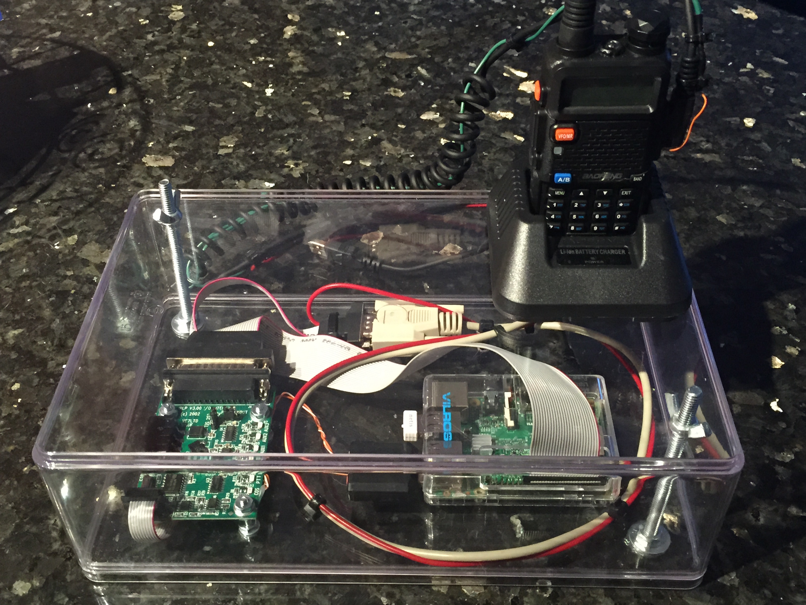
Above are a couple photos of the end result of my effort, and IT ACTUALLY WORKS! My setup transmits on low power (1 watt) into a modest UHF ground-plane antenna. It has a range of just under 1 mile which is perfect for me to stay connected while walking the dogs around the neighborhood carrying a second Baofeng UV5R.
Here’s a pic of my original Raspberry Pi IRLP/UV5R node setup with the radio still in it’s original case. It worked well, except there just isn’t any way for the heat it generates to get out of the radio housing.
Note that I am not going to detail how to configure and setup a Raspberry Pi or an IRLP node here. There are already several sites dedicated to those tasks online. I’m going to focus on the modifications I did to the UV5R node radio to make it a viable solution for long term 24/7 use.
There are also several tutorials already online which show how to wire the Baofeng UV5R as a node radio. Here’s one in particular that I found helpful. It clearly shows where to surface solder the COS wire to the UV5R circuit board. It also shows the correct wiring to interface the speaker/mic ports on the radio to a DB-9 serial port cable. http://www.ka1mzy.com/RPI-IRLP-SETUP.html
Everything up to this point is well documented via Google and YouTube searches. What I couldn’t find online was a way to modify the UV5R in such a way so as to keep itself cool even under a heavy transmit cycle. I knew this would involve getting it to power up outside of it’s case. This presented a secondary problem. I wanted the node radio to run off a standard 12v DC power supply, but the UV5R runs off 8v DC. With the case removed, there was no longer anything to hold the battery in place, so powering it with the battery was no longer an option.
When I first set out on this project, I had no idea how well it would work. Not knowing if it would be successful, I didn’t take step by step pics of the build process. So I am going to share some limited pics of the completed node radio and try my best to explain what is shown. If someone else decides to take up a similar build project, and would like to photograph the build process, I would gladly accept any photos you can provide and give credit to whoever provides them.
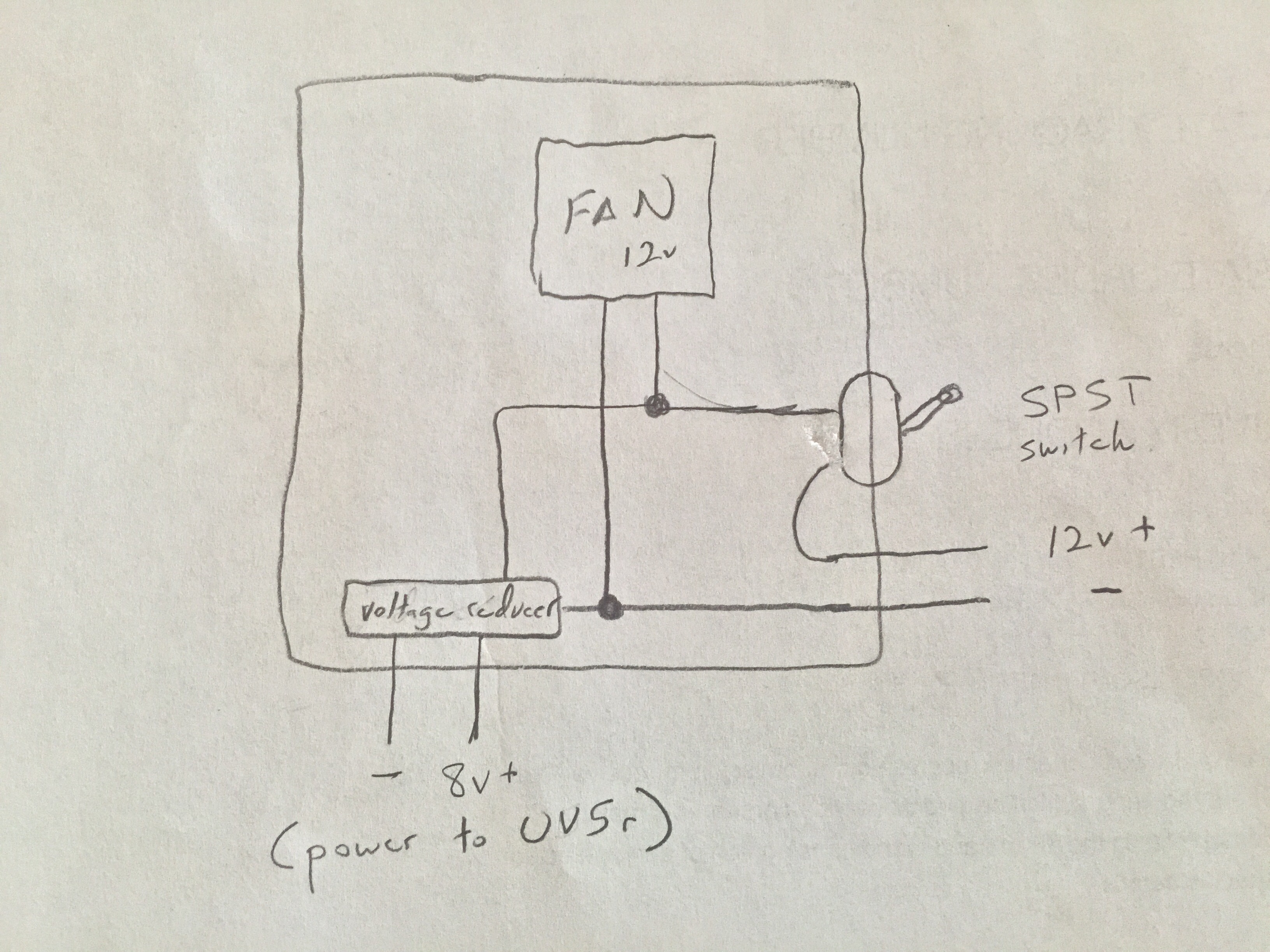
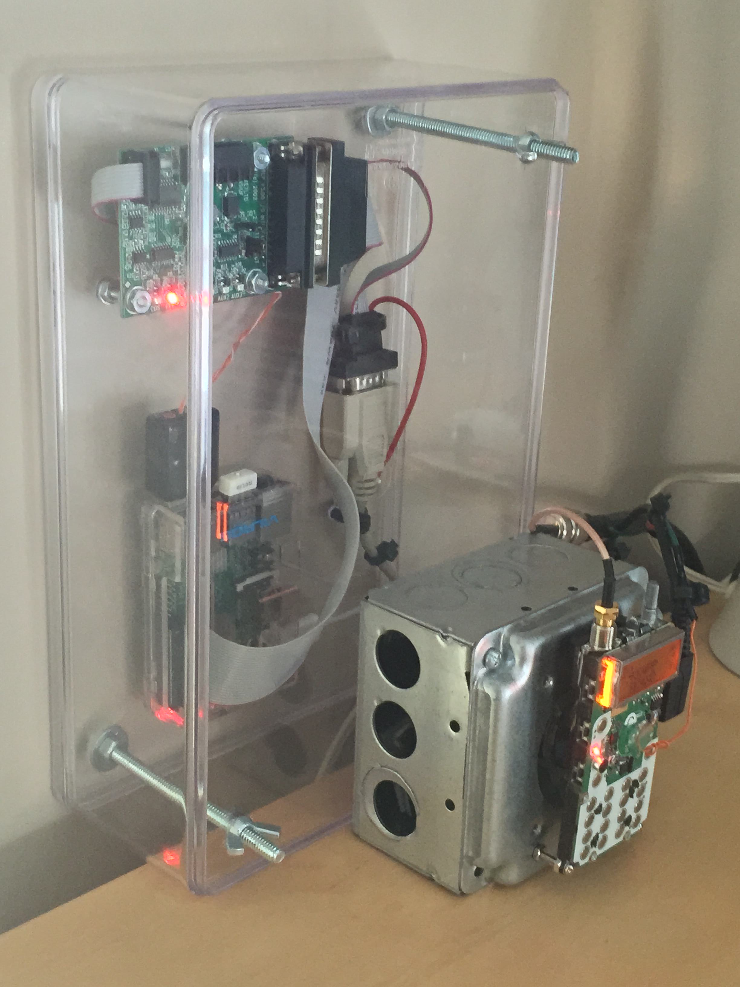
Here are a couple photos of the inside of the completed node radio housing and a sketch of a crude wiring diagram I drew during the design process:


The node radio housing is a basic 3.5″ electrical box I picked up at The Home Depot. The 12v wires to the power supply are held in place by a romex connector on the lower right. All the knock outs on both sides are removed to allow for airflow. The front cover that the UV5R is screwed to has a 2″ round opening in the middle. I believe this cover is intended to be used with a 220v US outlet which would be used for a kitchen range, electric dryer, etc. (You can’t really see the round opening in the above photo as it is covered by the cooling fan.)
The switch is a standard SPST toggle switch that I picked up at Radio Shack. There are many styles available. Pick the one you like best.
Here’s the model of 80mm cooling fan I chose from Amazon. Cooling Fan Any similar fan should work. $3 with free shipping was hard to beat though! I connected it to a 12v power supply to verify which way the blades turn prior to mounting. (You don’t want it blowing in the wrong direction!) It has a 3 speed switch. I use the lowest setting which is almost completely silent. I was surprised at how little airflow was really needed to keep the UV5R cool. It is glued into place with a dab of hot melt glue in each of the four corners. Don’t glue it in place until the UV5R is permanently mounted to the box cover, as you’ll need access to the mounting screws behind it.
The cooling fan runs off 12v DC, but the UV5R requires 8v DC. I stepped down the voltage using the guts from the inside of this battery eliminator also from Amazon. Here again, $6 shipped was hard to beat! Battery Eliminator I cut the cigar lighter and most of the wire off and it cracked open easily with a pocket screwdriver. I didn’t want it to come in direct contact with the metal node radio housing so I glued a portion of the plastic case to the back of the electrical box housing. After wiring, I then glued the eliminator circuit and heat sink to the piece of black plastic inside the metal housing. The wiring was pretty straightforward per the above diagram. It has a red and black wire in and a red and black wire out.
The UV5R is a really easy radio to disassemble. A quick YouTube search pulls up several excellent disassembly videos. https://www.youtube.com/results?search_query=uv5r+disassembly
The two 8v output wires from the battery eliminator connect directly to the terminals on the back of the UV5R. The UV5R battery terminals are gold plated and it was very easy to solder to wires to them. I fed these wires back through the romex connector on the side of the electrical box and then soldered them to the eliminator circuit (after mounting the UV5R to the metal cover). Here’s a rather poor picture of the wires soldered to the battery terminals. Note that the positive wire connects to the side closest to the mic/speaker ports.

Mounting the UV5R to the metal cover was really easy. The top of the radio is mounted using the two belt clip screws that came with the radio. I carefully measured the hole spacing and drilled two small holes in the metal cover. The metal cover is about the same thickness as the original plastic UV5R housing, so the original belt clip screws worked perfectly.
The bottom of the UV5R is held in place by (2) #4 machine screws and (6) nuts. I temperarily mounted the radio using the top screws, dropped the machine screws through the existing case holes in the bottom of the radio and marked where they landed on the electrical box cover. Remove the radio, drill the holes, reinsert the 2 screws through the existing holes in the radio, secure them with one nut each, and then use the remaining nuts to secure the bolt ends to the metal cover. (Use nuts on BOTH sides of the metal cover.)
Here are a couple photos showing the mounting:


I mentioned it earlier, but this is the point where you would glue the fan to the back of the housing cover–after the UV5R is permanently mounted to the cover and when your wiring is basically complete.
That’s about it! Attach the metal cover to the metal housing. Attach the 12v wires to any 12v power supply and flip the switch. On the low power setting, it will run cool 24/7. Mine has been running for several weeks now with a heavy transmit duty cycle courtesy of the WIN System reflector.

Approximate cost of materials: $48
Baofeng UV5R (Amazon)–$25
Battery Eliminator (Amazon)–$6
Fan (Amazon)–$3
Electrical box and cover (Home Depot)–$5
Switch (Radio Shack)–$4
Screws and nuts (Radio Shack)–$5
Wires, solder, glue, etc were all stuff I had laying around the shack.
Some random thoughts:
I tried using the UV5R on both UHF and VHF. I found 70cm UHF vastly superior for my purposes. In an urban area, with lots of buildings to penetrate, I found UHF had twice the range of VHF in my neighborhood. Someone in a more open area may have better success with VHF though.
I used a scrap of wire from inside the unused portion of the DB-9 serial port cable as the COS wire.
Once you get the COS wire soldered to the circuit board, put a tiny piece of paper or electrical tape behind it to keep it from touching adjacent terminals. Once you verify that everything is working, cover the wire with hot melt glue to protect the soldered joint.
Once removed from it’s case, the LED backlighting on the keypad is blindingly bright. It will light up a room. I covered the 4 LEDs with a dab of liquid electrical tape to block out the light.
Remember that if you want to program the radio using PC software (I use Chirp), you’ll need to be able to remove the speaker/mic connection plugs. Do so carefully. It would be a shame to get the hole thing assembled and then tear off the COS wire while trying to program the node radio. Program several UHF & VHF frequencies into it along with CTCSS tones and hopefully you’ll never have to program it again.
And finally, let me know what you think! Feel free to email, post comments and share this page with others who might find it useful. If you do attempt a similar build, take lots of pics and send them to me at jaygray@bellsouth.net. I’d love to add them to the build page.
Hope to hear you on the air!
Jason
KK4PP

I like your set up. Very informative post. Thanks. NP3QL.
LikeLiked by 1 person
Is the CMS relevant to the TX or RX end? I only ask because if I want a 2 USB fob/ 2 radio full duplex repeater rather than half duplex, which radio would the cos soldering NOT be required on?
LikeLike
I believe the COS wire is required on the “transmitting radio” (the one you are listening to) so that it can key the PTT circuit. I attempted a VOX setup using only the mic/speaker connectors on the side of the radio and it was problematic at best. Added the COS wire and problem solved. I believe the “receiving radio” (the one you transmit to when you want to talk) would only require a connection to the external speaker jack. Hopefully that “transmitting radio/receiving radio” terminology makes sense. It’s backwards from what you would think your twin node radios would be called. 73! KK4PP
LikeLike
Is it right that on the Amazon page of the battery eliminator an image shows that the stepdown circuit is build into the cigarette lighter instead of inside the battery?
I’m planning on using a UV-5R for APRS in my car.
Thanks in advance.
73,
PD8DA
LikeLike
The unit I purchased had the circuit inside the “fake” battery that attaches to the radio, however, the pic on Amazon now shows a model with the circuit inside the lighter assembly itself. Unfortunately, I would say there is a 50/50 shot as to which model you receive depending on the seller that you order from. I ordered mine from “Honbow”, but they are not currently listed as a seller. Sorry, I can’t help you more. de KK4PP
LikeLike